Free and guided movement
Defined wheel paths
Fixed footprints and datums
Named acceptance methods
The robots arrive next Monday. The floor has handled forklifts for fifteen years. Why would it suddenly become a design problem?
That question comes up late on a lot of automation projects. A conventional warehouse tolerates conditions that a high-cycle automated system notices immediately. Among them are a small joint step crossed thousands of times a shift, a cross-aisle slope that leans a tall load, a polished patch that changes wheel traction, and gradual settlement that shifts a fixed grid away from its datum. The slab can be structurally sound and still be operationally incompatible with the machine about to run on it.
So the right question isn’t “Is the floor flat?” It is whether the existing or proposed floor provides the geometry, continuity, surface behaviour and structural support this automation system needs, at its actual speed, payload and movement pattern. That is what a warehouse automation floor readiness assessment answers.
Core engineering principle. Automation readiness is a compatibility study. The governing requirement comes from the actual equipment, route and structural interface. Published floor standards provide the measurement framework, but the OEM or project specification may impose different or additional limits.
A floor survey can generate millions of measurements and still answer the wrong question if nobody knows what the equipment will do. Before selecting a standard or an instrument, we collect the automation inputs that translate directly into floor sensitivity.
Free roaming, guided path, fixed grid or fixed supports. Wheelbase, track width, wheel count and diameter, caster arrangement, lift height, payload height, centre of gravity and allowable mast lean.
Speed, acceleration, braking, turning radius, docking accuracy and traffic frequency. Wheel material, contact pressure, traction-control logic and sensitivity to steps, joints or debris.
LiDAR/SLAM, QR or fiducial markers, magnetic or wire guidance, reflectors, vision or hybrid. Rack legs, grid columns, rails, conveyors, ports, chargers and concentrated support reactions.
Freezer conditions, washdown, contamination, dust control, ESD-sensitive product and cleaning chemistry, plus the document that governs. That means the OEM spec, integrator spec, structural criteria and the named floor standard, with edition.
Three automation families can share one building and still need completely different descriptions of the floor. Calling all of it “robotics” is where readiness studies go wrong.
AMRs and free-routing AGVs. Many possible wheel paths; a local defect can be hit from several directions. Measure area-based geometry plus local defects, joints and surface behaviour. OEM criteria govern.
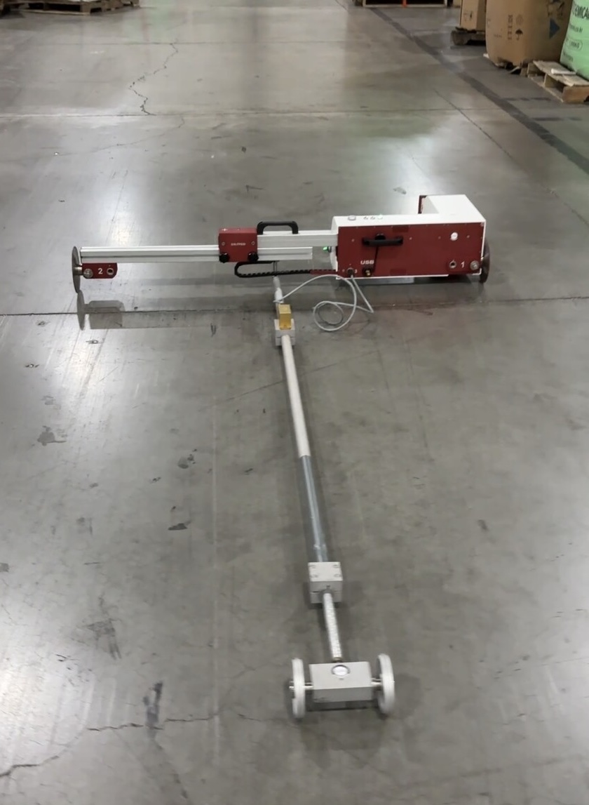
VNA turret trucks and rail, wire or magnetic guided paths. The same wheels follow the same tracks every cycle. Measure directly in the actual wheel paths, using Fmin, TR34 DM, VDMA or the project/OEM method.
AutoStore and grid systems, ASRS supports, rack and rail systems. Equipment is tied to a support grid, rail or datum. Dense elevation mapping, structural support checks and OEM footprint tolerances.
Why this matters: ASTM E1155/E1155M-23 states that FF/FL results are used primarily for randomly trafficked floors and should not be used to enforce tolerances on floors intended primarily for fixed-path vehicle systems. For defined traffic, measure the paths the wheels will actually follow.
A useful readiness study treats the floor as four interacting layers. A pass in one cannot cancel a failure in another. A structurally adequate slab can have unacceptable joint steps, a geometrically excellent floor can carry a coating too slippery for the selected wheel, and a smooth surface can still move under concentrated load.
What shape does the machine see? Flatness, levelness, waviness, cross-slope, abrupt elevation changes and relationship to datum, sampled at the gauge length that matches the machine rather than one global number.
Where continuity is interrupted. Width, step, edge condition, movement, load transfer and crossing angle. For brownfield work the key deliverable is a joint-by-joint defect map tied to robot routes.
The robot does not drive on a number. The top few millimetres form the wheel and sensor interface, covering friction, micro-roughness, abrasion, dusting, gloss, cleanliness, ESD and moisture.
Can the slab carry the automation? Fixed racks, grids, rails and ASRS structures bring concentrated reactions, settlement limits and sustained loads the original warehouse never saw.
A small floor error becomes a large machine error. If the left and right wheel tracks of a VNA truck differ by 2 mm across a 1.5 m track width, the cross-aisle angle is roughly 1.33 mrad. Project that to a 12 m lift height and the geometric lateral offset is about 16 mm, before tire deflection, mast flexibility, dynamic motion and load movement are added. This isn’t a substitute for the truck manufacturer’s stability model; it shows why a few millimetres at the floor matter at height.
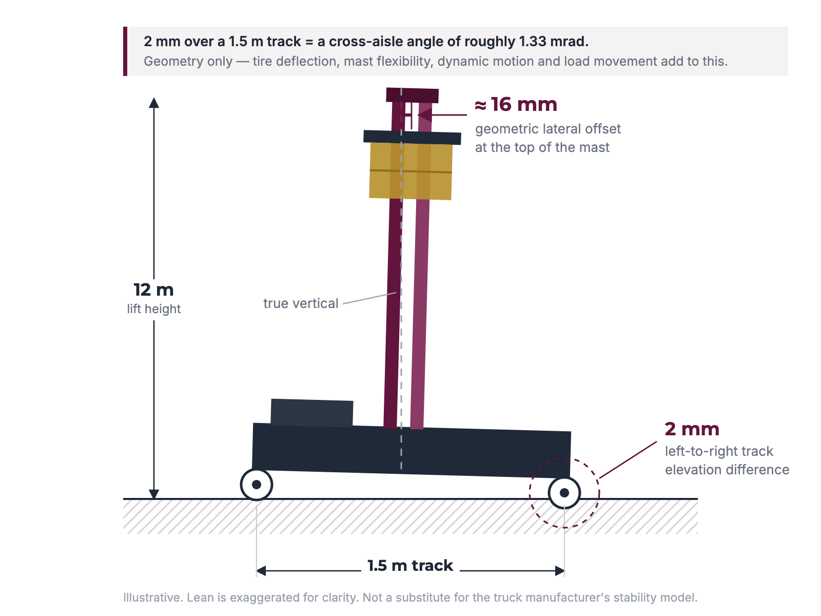
Cross-aisle elevation difference projected to mast height. Lean is exaggerated for clarity. Click to enlarge.
Depending on the system, the readiness study may need to characterize the surface as well as the geometry. Each property comes with a caution, because there is no universal robot value for any of them.
Will the wheel accelerate, brake and turn predictably? Specify both the test method and the acceptance value; there is no universal AGV/AMR coefficient.
Does microtexture support traction without wheel wear or vibration? Coating-prep CSP is not a robot ride-quality metric.
Could reflective or non-uniform areas affect optical navigation or cameras? ISO 2813 measures gloss; the acceptable value is an OEM requirement.
Will repeated routes create wear, fines or wheel contamination? Abrasion tests are comparative; they do not predict years of service.
Does the process require controlled floor resistance? Project-specific, coordinated with the grounding strategy, and only where the product or OEM requires it.
Can a planned coating, levelling layer or ESD finish be installed reliably? Use the manufacturer’s limits and a defined method such as ASTM F2170.
Structure note: one public AutoStore FAQ gives a 16-bin-high, 30 kg-per-bin configuration requiring 2,000 kg/m² (409 lb/ft²) floor strength. That is an example for a stated configuration, not a universal design value. Project loads and misalignment criteria come from the current OEM/integrator package and are reviewed with the structural engineer. A surface-readiness conclusion never implies structural adequacy unless structural evaluation is in scope.
A dense point cloud can be extremely useful and still be the wrong contractual calculation for a specified wheel-path method. An excellent FF/FL report can say almost nothing about a VNA wheel path that was never directly measured. We match the method to the acceptance question.
Randomly trafficked slab flatness and levelness. Exact edition, sampling plan and minimum local criteria reported.
Known VNA/AGV wheel paths. Track geometry configured to Fmin, TR34 DM, VDMA or the project method.
Precise elevations, datum networks, control and support points, with documented closure and calibration.
Dense topology, high/low mapping, transitions and remediation planning. Not automatically an E1155 or defined-path test.
Joint step, gap, local transition and microtexture, with stated resolution and acceptance rule.
Automation gets specified around throughput and payload. The floor it runs on is usually assumed to be adequate because it has carried forklifts for years. That assumption is the most expensive one on the project.
By the time the robots arrive, the floor is under racking, under power and under a schedule. A tolerance problem found at commissioning stops being a concrete question and becomes a shutdown, a crane rental and a re-pour in a live building. Measuring first moves that discovery to the point where the correction is still local, planned and cheap.
It also settles the question with data rather than opinion. Without measurements, the conversation between the client, the integrator and the flooring contractor runs on assertion, and the risk transfers quietly to whoever signs last. With a survey tied to the named acceptance method and the routes the equipment will actually run, everyone works from the same evidence and remediation is scoped to the zones that need it.
Find it on paper, not at commissioning. Every other version of this conversation happens after the racking is up, the power is in and the schedule is fixed.
One asks “How do I specify it before the pour?” The other asks “Can this floor work?”
The least expensive millimetre to correct is the one that never gets built. Automation criteria should shape slab design, pour layout, joint locations, finishing method, survey plan and acceptance timing before placement begins. We help the design team decide which areas are random traffic, which are defined traffic and which carry fixed equipment footprints, so each zone gets the correct measurement and acceptance method.
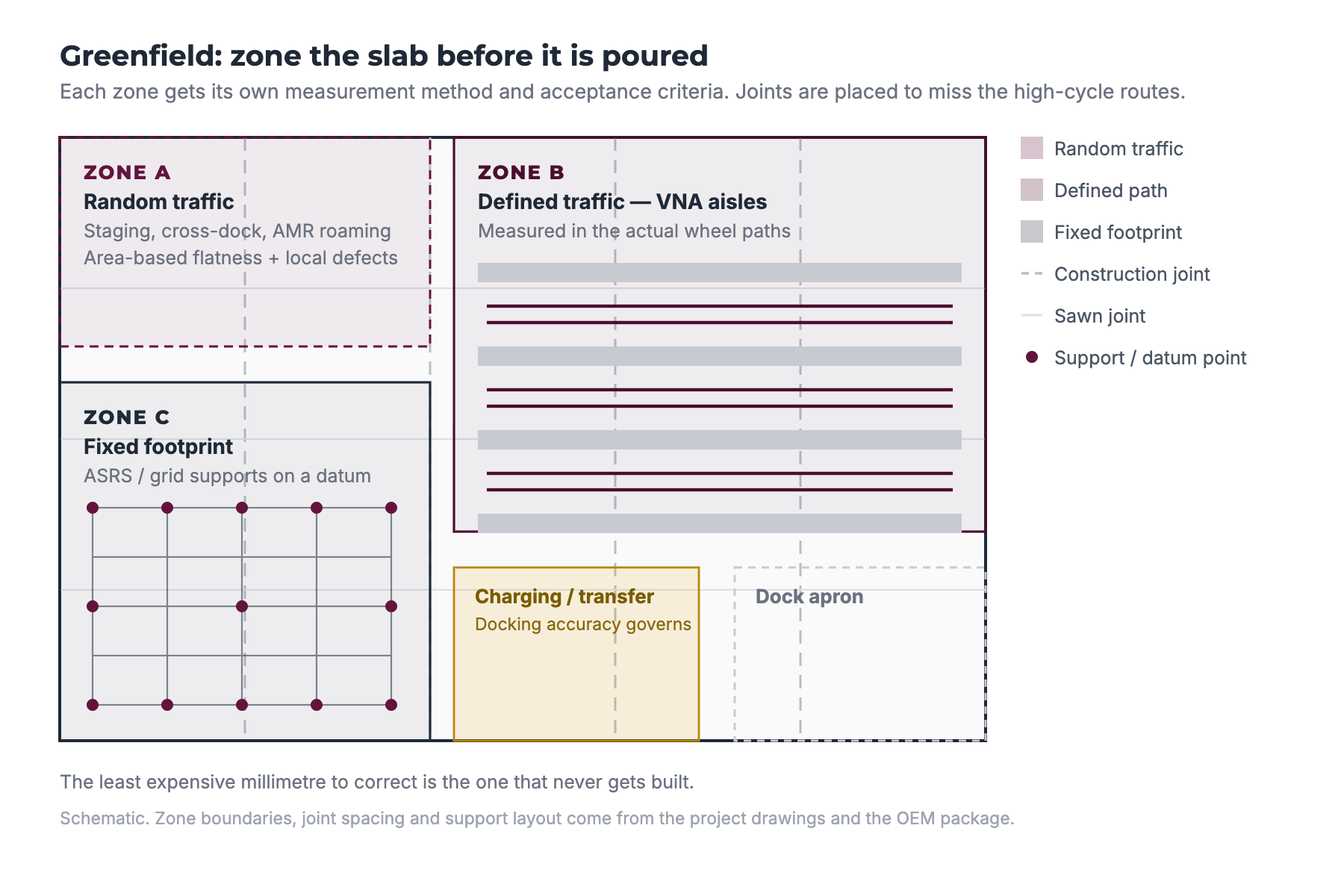
Pour and joint layout with the three traffic zones marked. Click to enlarge.
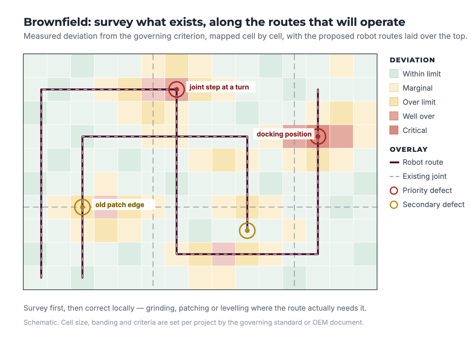
Readiness heat map with the proposed robot routes overlaid. Click to enlarge.
A brownfield assessment starts with the proposed equipment footprint and route map, overlaid on the existing slab, joints and previous repairs. The field program then prioritizes the high-cycle zones. Those are narrow aisles, turns, docking and charging positions, transfer points, ports and conveyor interfaces. AutoStore’s own brownfield guidance makes the same point. Survey first, then correct locally with grinding, patching or levelling.
Collect OEM/integrator criteria, drawings, route or footprint, loads, navigation, wheel geometry and operating conditions.
Measure the properties that correspond to the machine, covering geometry, joints, surface tests and structural investigation as required.
Compare measured conditions to the named requirement, zone by zone. Separate non-compliance from advisory observations.
Grinding, patching, joint repair, overlay, surface treatment or structural work by defect type. Localized correction wherever it is sufficient.
Re-measure corrected zones with the same governing method. Pre- and post-remediation data preserved.
Archive route maps, point clouds, profiles, joint inventory and surface data so future changes can be told apart from original conditions.
Every surveyed zone lands in one of three states. The status tells the project team what happens next, and keeps a correctable surface issue from being confused with a structural or specification problem.
Measured condition meets the named acceptance criteria for the zone. No critical geometric, surface or structural exceptions in scope.
Next: preserve the baseline and proceed to commissioning checks.
A defined property is outside the limit but has a practical correction path. That covers localized high spots, joint steps, patch edges, a surface treatment issue or a correctable levelling zone.
Next: design the correction, execute, re-test with the same method.
The floor may be incompatible, or the requirement is incomplete. Typical causes are a structural or settlement concern, conflicting standards, missing OEM limits, extensive movement or uncertain slab construction.
Next: resolve criteria or structural design before accepting a remediation method.
Ten questions, about two minutes. You get an indicative readiness tier and we get enough to brief the right engineer before we call.
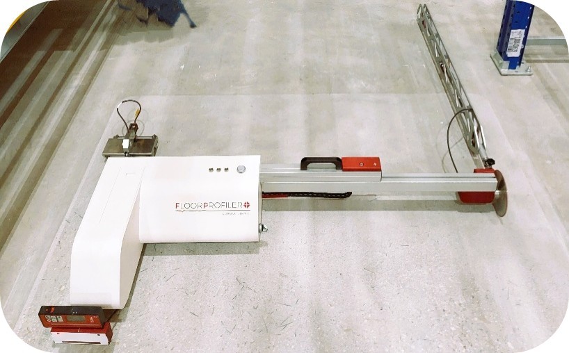
FF/FL, Fmin and defined-path profiling with the FloorProfiler.
Localized and full-aisle correction to defined-movement tolerances.
Rebuild joint edges and eliminate steps on high-cycle robot routes.
Address settlement and support where fixed equipment needs a stable datum.
Guide-path installation for defined-movement VNA systems.
Industry overview for AGV, AMR and ASRS facilities.
Yes. FF/FL describes statistically sampled flatness and levelness for randomly trafficked floors. A fixed-path VNA system, a local joint step, a traction problem or a fixed equipment datum requirement can all remain unacceptable even when the area-level FF/FL report is strong.
There is no universal number. The governing value comes from the AMR manufacturer for that model, at its actual speed, payload and lift height. It is usually a local limit rather than an area statistic, stated as a maximum step, gap or slope over a given distance. We start from the OEM document and choose the measurement that tests it.
Generally no. E1155 itself states that FF/FL is intended for randomly trafficked floors and should not be used to enforce tolerances on floors intended primarily for fixed-path vehicle systems. VNA aisles are defined traffic, so they are measured in the wheel paths using Fmin, TR34 DM, VDMA or the method the project names.
Not for a contractual defined-path result. Scanning is excellent for dense area mapping, high/low visualisation, transitions and remediation planning. It is not automatically an E1155 or a defined-path calculation, and if the specification names a wheel-path method then the wheel path has to be measured with an instrument configured for it. The two are complementary, not interchangeable.
Start with the routes the equipment will actually run. Narrow aisles, turns, docking and charging positions, transfer points and conveyor interfaces come first, then joints and previous repairs where they cross those routes. A building-wide average is the last thing to look at.
Usually yes. A forklift crosses a joint occasionally and its operator absorbs the step. An automated vehicle may cross the same joint thousands of times a shift, always at the same point, with a smaller, harder wheel and a sensor package that reads the disturbance. Edge condition, step and load transfer matter far more as a result.
Before the slab is designed, and then again at the acceptance stage. Automation criteria should shape pour layout, joint locations, finishing method and the survey plan itself. Surveying only after placement leaves correction as the single remaining option.
How Ready Is Your Floor For Automation?